Physical Address
Arthur Avenue , BrookField , ILLINOIS , 60513 , United State
Physical Address
Arthur Avenue , BrookField , ILLINOIS , 60513 , United State

Modern construction equipment, agricultural machinery, mining machines, trucks, buses, and industrial engines rely on dozens of Electronic Control Modules (ECMs) communicating through high-speed data networks. Every time an electronic system detects an abnormal condition, it stores diagnostic information using standardized fault identifiers.
If you have ever connected CAT Electronic Technician (CAT ET), Cummins INSITE, John Deere Service Advisor, Volvo Tech Tool, JCB ServiceMaster, Komatsu Diagnostic Tool, Scania SDP3, MAN CATS III, Hino DX2, Isuzu IDSS, or any other OEM diagnostic software, you have certainly encountered abbreviations such as SPN, FMI, MID, and CID.
Although these abbreviations appear simple, they form the foundation of modern heavy equipment diagnostics. Understanding them correctly allows technicians to identify not only the component involved, but also the exact nature of the failure, the controller reporting it, and the diagnostic path recommended by the manufacturer.
This guide explains every diagnostic identifier in detail using real-world examples from Caterpillar, Cummins, Volvo CE, Komatsu, John Deere, Perkins, Detroit Diesel, Mack, Scania, Mercedes-Benz Trucks, Liebherr, CASE, New Holland, Bobcat, Kubota, Hitachi, Hyundai, Doosan, Kobelco, SANY and many other manufacturers.
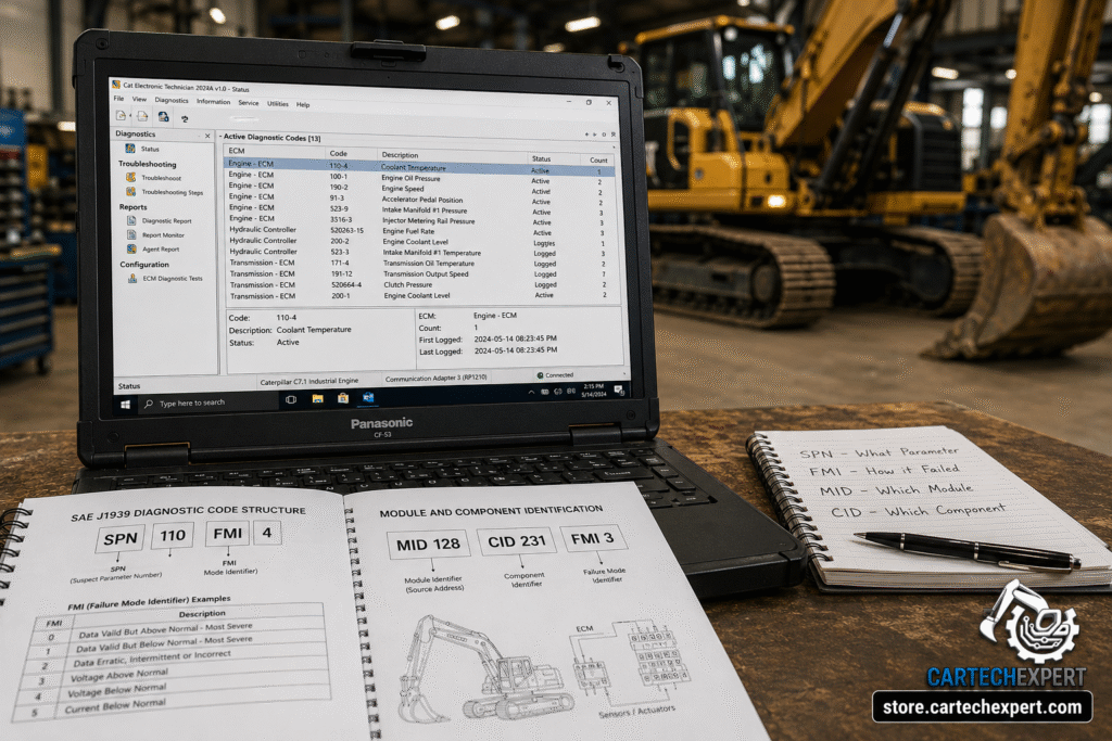
| Abbreviation | Meaning | Main Purpose |
|---|---|---|
| SPN | Suspect Parameter Number | Identifies the parameter or sensor reporting a fault |
| FMI | Failure Mode Identifier | Describes the type of failure detected |
| MID | Module Identifier | Identifies which electronic controller reported the fault |
| CID | Component Identifier | Identifies the individual component on legacy diagnostic systems |
Today’s heavy equipment is dramatically different from machines produced twenty years ago. Modern excavators, bulldozers, loaders, articulated trucks, agricultural tractors, harvesters, and mining machines contain dozens of interconnected Electronic Control Modules.
Instead of operating independently, every controller exchanges information through communication networks such as SAE J1939, allowing engines, transmissions, hydraulic systems, braking systems, aftertreatment systems, dashboards, GPS modules and telematics controllers to communicate continuously.
Every second, thousands of electronic messages travel across the CAN Bus network. These messages include:
Whenever an Electronic Control Module detects abnormal operating conditions, it stores a Diagnostic Trouble Code (DTC). A DTC is much more than a simple fault number. It contains structured information describing:
Professional OEM software such as CAT ET, Cummins INSITE, John Deere Service Advisor, Volvo Tech Tool and Komatsu Diagnostic Tool interpret these values automatically, allowing technicians to troubleshoot efficiently without manually decoding hexadecimal communication messages.
SPN stands for Suspect Parameter Number. It is one of the most important concepts in SAE J1939 diagnostics because it identifies exactly which parameter, sensor, actuator or calculated value has generated the fault.
Think of the SPN as the “name” of the item experiencing a problem. Instead of displaying only a generic code, the controller references a standardized parameter number so that diagnostic tools from different manufacturers can interpret it consistently.
For example, an SPN may refer to engine coolant temperature, engine oil pressure, fuel rail pressure, accelerator pedal position, intake manifold pressure, battery voltage, turbocharger boost pressure, crankshaft speed, or hundreds of other monitored values.
| Example SPN | Parameter |
|---|---|
| SPN 110 | Engine Coolant Temperature |
| SPN 100 | Engine Oil Pressure |
| SPN 190 | Engine Speed |
| SPN 91 | Accelerator Pedal Position |
An SPN alone does not indicate what is wrong. It only identifies the parameter being monitored. To understand the actual problem, it must be combined with an FMI (Failure Mode Identifier), which explains the type of fault detected.
FMI stands for Failure Mode Identifier. While the SPN tells the technician what parameter is involved, the FMI explains how that parameter has failed. Together, the SPN and FMI create a complete diagnostic picture and are the foundation of modern SAE J1939 troubleshooting.
For example, two machines may display the same SPN for engine coolant temperature, yet one reports that the signal is above normal while the other indicates the circuit is open. The SPN remains the same because the parameter is identical, but the FMI changes because the type of failure is different.
| FMI | Description | Typical Cause |
|---|---|---|
| 0 | Data Valid But Above Normal Operating Range – Most Severe Level | Critical overheating, overpressure, overspeed |
| 1 | Data Valid But Below Normal Operating Range – Most Severe Level | Extremely low pressure or temperature |
| 2 | Data Erratic, Intermittent or Incorrect | Loose connectors, damaged wiring, electrical interference |
| 3 | Voltage Above Normal | Short to battery, charging system problems |
| 4 | Voltage Below Normal | Open circuit, poor ground, damaged wiring |
| 5 | Current Below Normal | Open actuator circuit |
| 6 | Current Above Normal | Short circuit or failed actuator |
| 7 | Mechanical System Not Responding Properly | Sticking valves, worn components |
| 8 | Abnormal Frequency or Pulse Width | Speed sensor or timing signal problems |
| 9 | Abnormal Update Rate | Communication problems on the CAN Bus |
| 10 | Abnormal Rate Of Change | Rapidly fluctuating sensor values |
| 11 | Root Cause Not Known | General controller diagnosis |
| 12 | Bad Intelligent Device | Failed electronic module |
| 13 | Out Of Calibration | Sensor calibration required |
| 14 | Special Instruction | Follow OEM diagnostic procedure |
| 15 | Data Valid Above Normal – Least Severe | Minor over-range condition |
| 16 | Data Valid Above Normal – Moderately Severe | Warning before shutdown |
| 17 | Data Valid Below Normal – Least Severe | Minor under-range condition |
| 18 | Data Valid Below Normal – Moderately Severe | Engine derate may begin |
| 19–31 | Manufacturer or SAE Reserved Definitions | OEM specific implementations |
Among all FMIs, technicians most frequently encounter FMI 3, FMI 4, FMI 5, FMI 6, FMI 7 and FMI 9. These usually point toward electrical issues such as damaged wiring, failed sensors, communication interruptions or defective actuators rather than mechanical engine failures.
MID stands for Module Identifier. Unlike the SPN, which identifies a monitored parameter, the MID identifies which Electronic Control Module (ECM) detected and reported the fault.
Modern heavy equipment often contains dozens of electronic controllers, including an Engine ECM, Transmission ECM, Hydraulic ECM, Brake Controller, Implement Controller, Cab Controller, Body Controller, Aftertreatment Controller and Instrument Cluster. When multiple modules communicate over the machine network, technicians must know which controller generated the diagnostic message.
| Typical Module | Purpose |
|---|---|
| Engine ECM | Controls engine operation |
| Transmission ECM | Controls transmission shifting |
| Hydraulic ECM | Controls hydraulic functions |
| Aftertreatment ECM | Manages DPF and SCR systems |
| Cab Controller | Controls operator interface functions |
| Instrument Cluster | Displays machine information and warnings |
Legacy Caterpillar machines commonly use MID, CID and FMI combinations. When using CAT Electronic Technician, technicians frequently see diagnostic entries such as:
MID 036 CID 0096 FMI 03
This immediately tells an experienced technician which module reported the fault, which component is involved and what type of electrical problem has been detected.
CID means Component Identifier. It is widely used on Caterpillar equipment and several legacy diagnostic systems. Rather than identifying a standardized SAE parameter, the CID references a specific component assigned by the manufacturer.
Examples include coolant temperature sensors, injector solenoids, fuel pressure sensors, turbo actuators, hydraulic solenoids, transmission valves, joystick sensors and dozens of other machine components.
| Diagnostic Format | Meaning |
|---|---|
| CID | Component being monitored |
| FMI | Failure detected on that component |
| MID | Controller reporting the failure |
Many Caterpillar machines continue to display MID/CID/FMI diagnostics even though newer platforms increasingly use standardized SPN/FMI reporting over the SAE J1939 network.
These identifiers should never be interpreted independently. A professional technician always reads the complete diagnostic message because every field contributes valuable information.
| Field | Question Answered |
|---|---|
| MID | Which controller reported the fault? |
| SPN or CID | Which parameter or component is affected? |
| FMI | What type of failure occurred? |
Consider the following example:
SPN 110 FMI 3
This indicates that the engine coolant temperature parameter is experiencing a voltage-above-normal condition. The fault may be caused by a short to battery, damaged wiring, connector corrosion, sensor failure or an internal ECM fault. A skilled technician would confirm the problem using live data, electrical measurements and the manufacturer’s troubleshooting procedure rather than replacing the sensor immediately.
Understanding how these identifiers interact dramatically reduces diagnostic time, prevents unnecessary parts replacement and leads to faster, more accurate repairs on modern heavy equipment.
One of the fastest ways to understand diagnostic codes is by examining real-world examples. Every day, technicians connect OEM software such as CAT ET, Cummins INSITE, Volvo Tech Tool, John Deere Service Advisor, Komatsu Diagnostic Tool, Allison DOC®, Detroit Diesel DiagnosticLink®, Scania SDP3 and other dealer applications to troubleshoot active and logged faults.
Although each manufacturer presents diagnostic information differently, the interpretation process remains nearly identical. The software reads the fault, identifies the affected controller, displays the parameter or component involved and explains the detected failure mode.
SPN 110 FMI 4
| Field | Meaning |
|---|---|
| SPN 110 | Engine Coolant Temperature |
| FMI 4 | Voltage Below Normal or Short to Ground |
Possible causes include a damaged coolant temperature sensor, broken wiring, poor connector contact, water intrusion or a short circuit to ground. Before replacing the sensor, technicians should inspect the connector, measure reference voltage, verify signal return and compare live data with actual engine temperature.
SPN 100 FMI 1
This fault indicates that engine oil pressure has fallen below the acceptable operating range. The root cause may be a genuine lubrication problem such as low oil level or a worn oil pump, but electrical issues such as faulty sensors or damaged wiring must also be considered before major engine repairs begin.
SPN 91 FMI 3
This diagnostic indicates excessive voltage on the accelerator pedal position circuit. Common causes include damaged wiring harnesses, moisture inside connectors, poor repairs, short circuits to battery voltage or a defective pedal position sensor.
SPN 190 FMI 2
The Engine ECM has detected an erratic or intermittent engine speed signal. Technicians typically inspect the crankshaft speed sensor, wiring harness routing, connector pins and sensor air gap before replacing components.
CAT Electronic Technician remains one of the most widely used OEM diagnostic applications in the construction, mining and industrial engine industries. When connected through the Caterpillar Communication Adapter III or Communication Adapter 3+, CAT ET reads active events, logged diagnostic codes, configuration parameters and live engine data.
Depending on machine generation, CAT ET may display either SPN/FMI diagnostics or Caterpillar’s traditional MID/CID/FMI format.
| Displayed Code | Interpretation |
|---|---|
| MID 036 CID 0096 FMI 03 | Specific controller reports a voltage-high condition on the assigned component. |
| SPN 100 FMI 1 | Engine oil pressure below acceptable operating range. |
| SPN 110 FMI 3 | Coolant temperature circuit voltage above normal. |
| SPN 190 FMI 2 | Engine speed signal erratic. |
CAT ET also provides troubleshooting instructions, wiring diagrams, service tests, injector cutout functions, cylinder performance tests, configuration programming and calibration procedures that help technicians verify the actual cause instead of replacing parts by trial and error.
Cummins INSITE primarily uses the SAE J1939 SPN/FMI diagnostic format. Each active code is accompanied by a detailed fault description, possible causes, repair instructions and links to OEM troubleshooting procedures.
Experienced Cummins technicians rarely rely only on the displayed code. Instead they analyze freeze-frame information, engine operating conditions, fault occurrence count and live sensor values before deciding on repairs.
Volvo construction equipment, Volvo trucks and Mack vehicles also rely heavily on SAE J1939 diagnostics. Tech Tool automatically decodes SPNs and FMIs while displaying controller information, live values, calibration options and guided troubleshooting procedures.
Because every electronic controller continuously exchanges information across the CAN Bus network, one failed sensor can generate several related faults in multiple controllers. Understanding communication architecture helps technicians identify the original root cause instead of repairing secondary symptoms.
Reading a diagnostic code is only the beginning of the troubleshooting process. Professional technicians follow a logical workflow designed to eliminate unnecessary parts replacement while reducing machine downtime.
Generic scan tools can often display only limited diagnostic information. Dealer-level software provides significantly more detail, including service tests, calibrations, injector coding, parameter programming, ECM replacement procedures, software updates, live data recording, event history and guided troubleshooting workflows.
Professional diagnostic applications such as CAT Electronic Technician, Cummins INSITE, John Deere Service Advisor, Komatsu Diagnostic Tool, Volvo Tech Tool, JCB ServiceMaster, Scania SDP3, Hino DX2, Isuzu IDSS, Allison DOC®, Detroit Diesel DiagnosticLink® and other OEM platforms dramatically improve diagnostic accuracy while reducing unnecessary downtime and repair costs.
Heavy equipment manufactured over the last three decades uses different communication standards depending on the machine’s production year. Understanding these protocols helps technicians correctly interpret diagnostic information and select the appropriate OEM software and communication adapter.
| Protocol | Main Application | Typical Diagnostic Format |
|---|---|---|
| J1708 / J1587 | Older trucks and equipment | MID • PID • SID • FMI |
| SAE J1939 | Modern heavy equipment | SPN • FMI |
| OEM Proprietary Networks | Manufacturer-specific systems | MID/CID/FMI or proprietary identifiers |
Although modern equipment has largely transitioned to SAE J1939, many fleets continue to operate legacy machines that rely on J1708/J1587 communications. Professional technicians often need to understand both systems because mixed fleets are common in construction, mining, agriculture and transportation industries.
Every OEM diagnostic application distinguishes between Active and Logged (Inactive) faults.
| Code Type | Description |
|---|---|
| Active | The failure currently exists and is being detected by the controller. |
| Logged / Inactive | The fault occurred previously but is not currently present. |
Active codes usually require immediate diagnosis because they represent an existing electrical or mechanical problem. Logged codes provide valuable historical information and can help identify intermittent failures that occur only under specific operating conditions.
Many Electronic Control Modules record operating conditions at the exact moment a fault occurs. This information, commonly known as freeze frame data, allows technicians to recreate the circumstances under which the failure happened.
Typical recorded values include engine speed, coolant temperature, fuel pressure, oil pressure, boost pressure, battery voltage, throttle position, machine hours, vehicle speed and engine load.
Instead of replacing components immediately, experienced technicians compare freeze frame values with live sensor readings to determine whether the fault resulted from an electrical problem, an operating condition or a genuine mechanical failure.
A large percentage of diagnostic trouble codes are caused by electrical issues rather than failed components. Thorough electrical testing should always be completed before replacing expensive sensors, actuators or Electronic Control Modules.
Yes. The SPN identifies the monitored parameter, while the FMI identifies the type of failure. The same parameter can experience different electrical or mechanical problems, resulting in different FMIs.
No. Many SPN/FMI combinations are caused by damaged wiring, poor grounds, connector corrosion, power supply problems or CAN Bus communication faults rather than defective sensors.
A single electrical problem, such as low battery voltage or a failed CAN Bus connection, may cause multiple Electronic Control Modules to lose communication simultaneously, creating numerous diagnostic codes.
No. Logged codes often provide valuable information about intermittent failures that may not be active when the machine arrives for service.
Generic diagnostic tools usually provide limited access. Dealer-level software offers complete fault descriptions, service tests, calibrations, parameter programming, software updates and guided troubleshooting procedures that generic tools cannot perform.
SPN, FMI, MID and CID codes form the language of modern heavy equipment diagnostics. Understanding how these identifiers work together allows technicians to diagnose construction equipment, mining machinery, agricultural equipment and commercial vehicles accurately while avoiding unnecessary component replacement.
Whether you are working with Caterpillar, Cummins, Komatsu, Volvo, John Deere, JCB, CASE, New Holland, Liebherr, Hitachi, Hyundai, Bobcat, Kubota, Scania, MAN, Mercedes-Benz Trucks, Hino, Isuzu or any other manufacturer, mastering diagnostic code interpretation is one of the most valuable skills for any professional field technician.
Combining OEM diagnostic software with proper electrical testing, service documentation and a structured troubleshooting process dramatically reduces downtime, lowers repair costs and improves first-time repair success.
© CarTechExpert • Professional Heavy Equipment Diagnostic Resources
