Physical Address
Arthur Avenue , BrookField , ILLINOIS , 60513 , United State
Physical Address
Arthur Avenue , BrookField , ILLINOIS , 60513 , United State

Last Updated: July 2026
| Quick Overview | |
|---|---|
| Technology | Controller Area Network (CAN Bus) |
| Standard | ISO 11898 |
| Invented By | Bosch GmbH |
| First Introduced | 1986 |
| Main Purpose | Communication between Electronic Control Units (ECUs) |
| Maximum Speed | Up to 1 Mbps (Classic CAN) |
| Extended Technology | CAN FD (Flexible Data Rate) |
| Used In | Cars, Trucks, Heavy Equipment, Agricultural Machinery, Marine, Industrial Automation, Military Equipment |
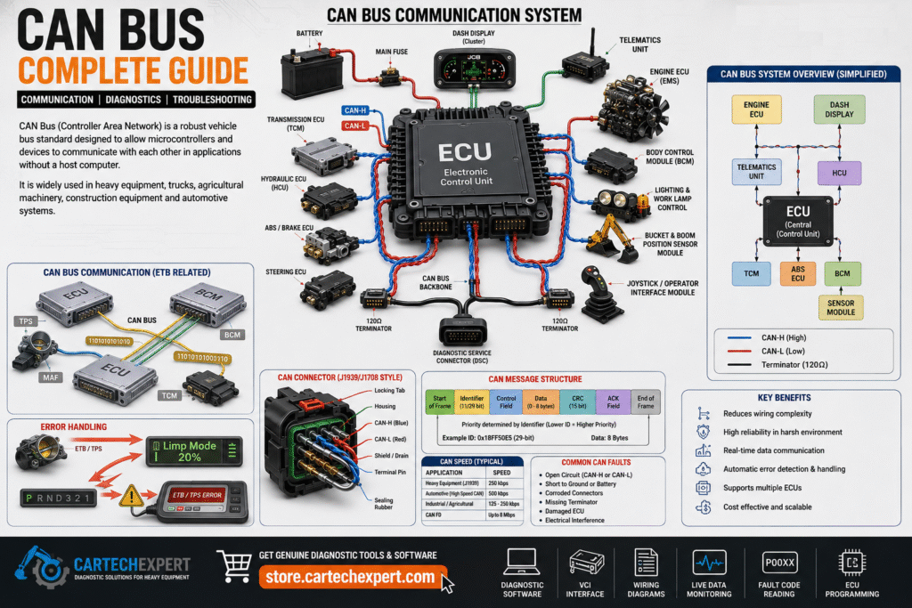
The Controller Area Network (CAN Bus) is one of the most important communication technologies ever developed for the automotive and heavy equipment industries. Every modern excavator, wheel loader, truck, agricultural tractor, mining machine and passenger vehicle relies on CAN Bus to allow electronic control units (ECUs) to exchange information quickly, reliably and safely.
Originally developed by Bosch in the 1980s, CAN Bus eliminated the need for complex point-to-point wiring by allowing multiple electronic controllers to communicate over just two wires. Today, it forms the backbone of nearly every electronically controlled machine manufactured by companies such as Caterpillar, Komatsu, Volvo CE, John Deere, Liebherr, Hitachi, SANY, Kobelco, Doosan, Hyundai, Bobcat, Takeuchi, Case, New Holland, JCB, Mercedes-Benz, Volvo Trucks, Scania, MAN, DAF and many others.
CAN Bus is a serial communication protocol that enables multiple electronic control units to exchange data over a shared communication network without requiring a central computer.
Every ECU connected to the network can both send and receive information. Messages are transmitted only when needed, reducing wiring complexity while maintaining high communication reliability even in electrically noisy environments such as construction sites and mining operations.
| Year | Milestone |
|---|---|
| 1983 | Bosch begins CAN development |
| 1986 | CAN protocol officially introduced |
| 1991 | First production vehicles use CAN |
| 1993 | ISO 11898 international standard published |
| 2000+ | Heavy equipment manufacturers adopt CAN |
| 2012 | CAN FD introduced |
| Today | Global communication standard for mobile machinery |
Before CAN Bus, every sensor and actuator required dedicated wiring between controllers. As machines became more complex, wiring harnesses became larger, heavier, more expensive and increasingly difficult to troubleshoot.
CAN Bus solved these problems by allowing every controller to share the same communication network.
A CAN network consists of multiple Electronic Control Units connected to two communication wires:
Instead of sending voltage directly to another controller, each ECU broadcasts a message onto the network. Every ECU listens continuously and processes only the messages relevant to its function.
Engine ECU

|

Hydraulic ECU

|

Transmission ECU

|

Instrument Cluster

|

ABS Controller

|

Telematics

|

Air Conditioning

|

Display Monitor

|

CAN-H -------------------------------

CAN-L -------------------------------
| Wire | Typical Voltage |
|---|---|
| CAN High | 2.5V → 3.5V |
| CAN Low | 2.5V → 1.5V |
Because CAN uses differential signaling, electrical noise affecting both wires equally is automatically cancelled, making CAN extremely reliable even in harsh environments.
Every CAN message contains several important fields:
CAN Bus uses message arbitration instead of assigning communication time slots.
The lower the message identifier, the higher its priority.
For example:
| Message | Priority |
|---|---|
| Brake Controller | Very High |
| Engine Speed | High |
| Hydraulic Pressure | Medium |
| Radio | Low |
| Application | Typical Speed |
|---|---|
| Passenger Cars | 500 kbps |
| Heavy Equipment | 250 kbps |
| SAE J1939 Trucks | 250 kbps |
| Industrial Automation | 125 kbps |
| High-Speed CAN | 1 Mbps |
| CAN FD | Up to 8 Mbps |
Modern construction equipment depends heavily on CAN communication.
Typical connected controllers include:
Heavy-duty trucks typically use SAE J1939, which operates over CAN Bus.
Controllers include:
Agricultural machines also rely extensively on CAN networks for engine management, transmission control, hydraulic systems, GPS guidance, automatic steering and precision farming systems.
CAN FD (Flexible Data Rate) is the evolution of Classic CAN.
Main improvements include:
Professional diagnostic software is the fastest way to identify communication problems.
Popular OEM diagnostic applications include:
A proper CAN network normally contains two 120-ohm termination resistors located at opposite ends of the communication bus.
When measured across CAN High and CAN Low with the system powered off, resistance is typically around 60 ohms.
Controller Area Network.
Bosch GmbH developed CAN Bus in the 1980s.
It allows multiple ECUs to communicate reliably while significantly reducing wiring complexity.
CAN FD is the next-generation version of CAN that supports higher data rates and larger message payloads.
Yes. A communication failure can prevent critical controllers from exchanging data, resulting in engine shutdown, hydraulic lockout or complete machine immobilization.
CAN Bus has become the universal communication backbone of modern heavy equipment, commercial vehicles and passenger cars. Its robust design, excellent resistance to electrical interference and efficient message-based architecture allow dozens of electronic controllers to operate together seamlessly. Understanding CAN Bus principles is essential for technicians, engineers and fleet managers who work with today’s electronically controlled machinery. Combined with professional OEM diagnostic software, CAN Bus diagnostics enable faster troubleshooting, reduced downtime and improved machine reliability.
