Physical Address
Arthur Avenue , BrookField , ILLINOIS , 60513 , United State
Physical Address
Arthur Avenue , BrookField , ILLINOIS , 60513 , United State

The definitive resource for heavy equipment technicians. Master JCB fault codes, understand DTC structure, and troubleshoot engines, hydraulics, and transmissions using official JCB ServiceMaster protocols.
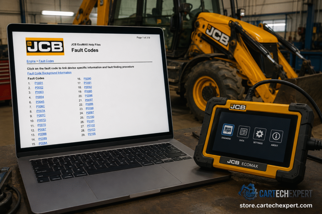
When a JCB machine throws a fault code, every minute of downtime costs money. As a heavy equipment diagnostic specialist, I can tell you that understanding JCB Diagnostic Trouble Codes (DTCs) is the difference between a 15-minute sensor swap and a full day of unnecessary component replacement.
JCB machines—from the iconic 3CX backhoe loader to the JS220 tracked excavator and Loadall telehandlers—use sophisticated electronic control systems. These systems communicate faults through standardized codes that follow the J2012 OBD-II structure, adapted for off-highway machinery.
JCB fault codes conform to the standardized 7-digit Diagnostic Trouble Code (DTC) format. Each character provides specific diagnostic information:
| Prefix | System Category | Typical Components |
|---|---|---|
| P0xxx, P1xxx | Powertrain | Engine, transmission, fuel system, aftertreatment (SCR, DPF) |
| B0xxx, B1xxx | Body | Cab controllers, HVAC, switches, instrument cluster |
| C0xxx, C1xxx | Chassis | Brakes, steering, suspension, hydraulic valves |
| U0xxx, U1xxx | Network / CAN Bus | Communication errors between ECUs, wiring harness faults |
The last two digits (6th and 7th characters) indicate the specific nature of the failure:
| FTB Code | Failure Description | Common Cause |
|---|---|---|
| 00 | General electrical fault / ADC error | Sensor internal failure, ECU analog input fault |
| 11 | Short circuit to ground (SC2GND) | Wiring rubbed through to chassis, connector corrosion |
| 12 | Short circuit to battery (SC2VBAT) | Wiring shorted to positive feed, internal sensor fault |
| 13 | Open circuit (OC) | Broken wire, disconnected connector, failed sensor coil |
| 16 | Circuit voltage below threshold | High resistance in wiring, weak power supply, bad ground |
| 17 | Circuit voltage above threshold | Voltage spike, alternator overcharging, sensor short |
| 19 | CAN bus message error / timeout | Network disruption, terminated ECU, corrupted data |
| 1A / 1B | Resistance too high/low | Injector coil degradation, wiring harness issues |
| 23 | Signal voltage low | Sensor drift, contaminated connector, reference voltage loss |
| 24 | Signal voltage high | Sensor shorted to reference, wiring cross-circuit |
| 2F | Signal erratic / noisy | Intermittent connection, EMI interference, sensor wear |
| 31 | General signal plausibility fault | Sensor out of rational range, mechanical system failure |
JCB engines, particularly the EcoMAX Tier 4 Final and Dieselmax series, generate the majority of powertrain fault codes. These codes cover fuel injection, air management, aftertreatment, and engine protection systems.
| DTC Code | SPN / FMI | Description | Effect | Primary Component |
|---|---|---|---|---|
| P0001 | 1076 / 5 | IMV (Inlet Metering Valve) driver fault detected | Torque Reduction | Inlet Metering Valve |
| P0002 | 521033 / 18 | Rail Pressure Negative Control Error during IMV-only control | Engine Stop | Inlet Metering Valve |
| P0087 | 109 / 16 | Rail pressure below target during delivery | Torque Reduction | High Pressure Pump / IMV |
| P0088 | 109 / 3 | Rail pressure above target – overpressure condition | Engine Stop | Rail Pressure Sensor / HPV |
| P0092 | 521167 / 3 | HPV (High Pressure Fuel Valve) driver fault in ECU | 60% Torque Available | High Pressure Fuel Valve |
| P0190 | 521032 / 10 | Rail Pressure Sensor signal gradient fault | 60% Torque Available | Common Rail Pressure Sensor |
| P0191 | 521032 / 4 | Rail Pressure Sensor below minimum threshold at key-on | 60% Torque Available | Common Rail Pressure Sensor |
| P0192 | 157 / 4 | Rail Pressure Sensor signal low fault | Limp Home (Idle Only) | Common Rail Pressure Sensor |
| P0252 | 1076 / 3 | Rail pressure control error – IMV current trim drift | Torque Reduction | Inlet Metering Valve |
| P0253 | 1076 / 18 | Low fuel flow detected through IMV | Engine Stop | Inlet Metering Valve |
| DTC Code | SPN / FMI | Description | Effect | Component |
|---|---|---|---|---|
| P0201-P0206 | Various | Injector circuit faults (Open Circuit, Short Circuit HSD-LSD) | Engine Stop / No Effect | Fuel Injectors (Cyl 1-6) |
| P0261-P0266 | 521090+ / 31 | Injector and wiring harness resistance fault (high/low/drop) | 60% Torque Available | Fuel Injector / Harness |
| P0263 | 651 / 18 | Cylinder balancing fault – injector stuck closed (Cyl 2) | 60% Torque Available | Fuel Injector #2 |
| P1104-P110B | 521095+ / 31 | No MDP (Minimum Drive Pulse) updates on injectors | 60% Torque Available | Fuel Injector Calibration |
| DTC Code | SPN / FMI | Description | Effect | Component |
|---|---|---|---|---|
| P0100 | 132 / 31 | MAF (Mass Air Flow) High Side Driver fault – OC or SC2VBAT | 60% Torque Available | TMAF Sensor |
| P0235 | 102 / 31 | Boosted air pressure sensor ADC fault | 60% Torque Available | VGT / Boost Sensor |
| P0237 | 521026 / 4 | Boosted air pressure sensor low fault | 60% Torque Available | VGT / Boost Sensor |
| P0400 | 2659 / 31 | EGR flow reached its calibrated limit | 60% Torque Available | EGR Valve |
| P0404 | 27 / 31 | EGR position learning failure | 60% Torque Available | EGR Actuator |
| P0470 | 1209 / 31 | Exhaust manifold pressure (P3) signal ADC fault | 60% Torque Available | Exhaust Pressure Sensor |
| P0544 | 1180 / 31 | Turbo inlet temperature fault | 60% Torque Available | Exhaust Manifold Temp Sensor |
| DTC Code | SPN / FMI | Description | Effect | Component |
|---|---|---|---|---|
| P2000 | 4364 / 19 | SCR conversion efficiency below threshold | Tier 4f Inducement Derate | SCR Catalyst |
| P202A | 3363 / 5 | DEF tank heater actuator open load | No Change | DEF Tank & Head Unit |
| P205C | 3031 / 4 | DEF tank temperature signal below minimum limit | Tier 4f Inducement Derate | DEF Tank Temperature Sensor |
| P207F | 3516 / 19 | DEF concentration message error from head unit | Tier 4f Inducement Derate | DEF Quality Sensor |
| P208A | 4374 / 5 | Supply module pump motor open load | No Effect | DEF Supply Module |
| P20E9 | 4334 / 0 | DEF overpressure error regardless of supply module state | Tier 4f Inducement Derate | Heated DEF Lines |
Hydraulic faults on JCB equipment typically manifest as C-codes (Chassis) or specific numeric codes on older machines. These codes relate to pressure sensors, solenoid valves, and pump controllers.
| Code | System Area | Description | Common Causes |
|---|---|---|---|
| Code 23 | Hydraulics | Hydraulic pressure sensor fault | Sensor failure, wiring short, pressure spike beyond calibrated range |
| C1xxx | Chassis / Hyd | Hydraulic solenoid circuit faults | Coil open circuit, connector moisture, ECU driver failure |
| C2xxx | Chassis / Hyd | Hydraulic pressure transducer out of range | Sensor drift, mechanical damage, contaminated fluid affecting sensor |
| C3xxx | Chassis / Hyd | Hydraulic pump proportional valve fault | Valve coil resistance out of spec, internal leakage, controller PWM failure |
Transmission Control Module (TCM) faults on JCB machines—particularly on Fastrac tractors, wheeled loaders, and backhoe loaders—require careful diagnosis as they often interact with engine torque management.
| Code | Description | Effect | Troubleshooting Priority |
|---|---|---|---|
| Code 37 | Transmission Control Module error | Limp mode / gear restricted | Check TCM power/ground, CAN bus continuity, software version compatibility |
| T003 | Transmission Control Module internal fault | Transmission disabled | Verify wiring harness integrity; check for software glitch requiring reflash |
| 101 | Transmission output speed sensor fault | Harsh shifting / limp mode | Inspect sensor air gap, check tone ring for damage, measure sensor resistance |
| P07xx | Transmission range/performance codes | Gear engagement failure | Check shift solenoid operation, clutch pack pressures, mechanical linkage |
On Tier 4i and newer JCB machines, error codes are divided into four primary lists: B-codes for the cab, C-codes for the chassis, P-codes for powertrain, and U-codes for the CANbus network.
| DTC Code | Description | Component |
|---|---|---|
| B1052-L2 | Cab controller switch input fault | Instrument panel switches |
| B1052-42 | Cab controller calibration / memory fault | Body Control Module (BCM) |
| B1xxx | HVAC temperature sensor circuit fault | Cabin heater / AC sensors |
| B2xxx | Seat / operator presence switch fault | Operator presence system |
| DTC Code | Description | Component |
|---|---|---|
| C1xxx | Chassis sensor supply voltage fault | Chassis ECU 5V/8V reference |
| C2xxx | Brake pressure sensor / switch fault | Service brake system |
| C3xxx | Steering angle / position sensor fault | Steering control system |
| C4xxx | Chassis solenoid driver fault | Attachment / auxiliary hydraulics |
Modern JCB machines rely heavily on CAN bus communication between the Engine ECU, Transmission ECU, Body Controller, and Aftertreatment DCU. U-codes indicate communication breakdowns that can cause cascading faults across multiple systems.
| DTC Code | SPN / FMI | Description | Effect | Component |
|---|---|---|---|---|
| U0029 | 521323 / 11 | CAN bus off error (250kbps network) | Communication Loss | DCU / Network Backbone |
| U0105 | 1440 / 19 | CAN message error for fuel quantity from engine ECU | 60% Torque Available | Engine ECU / CAN Bus |
| U010A | 521066 / 19 | CAN communication error: EGR CAN fault | No Effect | EGR Valve / CAN Bus |
| U0401 | 3224 / 19 | CAN message error for modelled NOx from engine ECU | Tier 4f Derate | NOx Sensor / Engine ECU |
| U040B | 521064 / 19 | Invalid data received from EGR control module | 60% Torque Available | EGR Control Module |
| U0140 | 3695 / 19 | Aftertreatment refresh inhibit/force switch message missing | No Change | Status Codes / CAN |
JCB ServiceMaster 4 is the gateway diagnostic application used by authorized JCB dealers and independent technicians. It provides a unified interface for accessing all vehicle support applications across JCB’s entire machine range.
Read and clear DTCs from all ECUs: Engine, Transmission, Hydraulics, HVAC, Chassis, and Aftertreatment. Fault codes are ranked by severity and include freeze-frame data.
Update ECU firmware, program injector codes, calibrate sensors, and perform parameter configuration. Supports Tier 4 Final and Stage V emission systems.
Real-time sensor values including rail pressure, boost pressure, DEF quality, EGR position, and hydraulic pressures. Graphing capabilities for intermittent fault capture.
Perform DPF regeneration, SCR system tests, injector cutout tests, hydraulic valve calibrations, and service interval resets directly through the software.
| Equipment Category | Supported Models |
|---|---|
| Backhoe Loaders | 1CX, 2CX, 3CX, 4CX, 5CX series |
| Tracked Excavators | JS115, JS130, JS160, JS200, 220X, 85Z-1, 86C-1, 100C-1 |
| Telehandlers (Loadall) | 525-60, 531-70, 535-95, 540-140, Tier 4 models |
| Wheeled Loaders | 407, 409, 427, 437, 457, Compact & Medium series |
| Fastrac Tractors | 4000 series, 7000 series, 8000 series, 8250 series |
| Skid Steer / RTFL | 135, 155, 190, 260, 926, 930, 940 |
As a diagnostic specialist, I follow this systematic approach when a JCB machine presents fault codes. This methodology minimizes guesswork and prevents unnecessary component replacement.
Connect JCB ServiceMaster 4 and record all active, pending, and historic codes. Note the freeze-frame data including engine RPM, temperature, and load conditions when the fault occurred. Do not clear codes yet.
Classify codes by effect:
Use the first character (P/B/C/U) to identify the affected system. For P-codes, consult the SPN (Suspect Parameter Number) to pinpoint the exact component. Cross-reference the FMI (Failure Mode Identifier) with the FTB to understand the electrical nature of the fault.
Inspect wiring harnesses for chafing, connector corrosion, and moisture ingress. JCB machines operate in harsh environments—wiring faults are more common than component failures. Check grounds at the chassis bonding points.
Test sensors with a multimeter or oscilloscope before replacement. Compare readings to the JCB service manual specifications. For injectors, measure coil resistance and compare across all cylinders. For pressure sensors, verify against a calibrated mechanical gauge.
After repair, clear codes and operate the machine through a full duty cycle. Re-scan to confirm the fault does not return. For intermittent issues, use ServiceMaster 4’s data logging feature during normal operation.
P0087 indicates “Rail Pressure Below Target During Delivery.” This means the common rail fuel system cannot achieve the commanded pressure. Common causes include a failing high-pressure fuel pump, a stuck Inlet Metering Valve (IMV), a leaking injector returning excess fuel, or a restricted fuel filter/lift pump. This code typically triggers torque reduction and should be addressed immediately to prevent engine damage.
On some older JCB machines, disconnecting the battery for 30 minutes may clear volatile memory codes. However, this is not recommended for Tier 4 Final machines with aftertreatment systems. Clearing codes without repair can trigger inducement derates. Always use JCB ServiceMaster 4 or a compatible diagnostic tool to properly read, diagnose, and clear fault codes while verifying the root cause is resolved.
SPN (Suspect Parameter Number) identifies the specific component or data parameter that has failed (e.g., SPN 110 = Coolant Temperature). FMI (Failure Mode Identifier) describes the type of failure (e.g., FMI 3 = Voltage High, FMI 4 = Voltage Low). Together, SPN and FMI provide precise diagnostic direction. JCB ServiceMaster 4 displays both values alongside the standardized P-code for complete troubleshooting context.
Limp mode (torque derate) is a protective strategy triggered by the Engine ECU when it detects a fault that could cause engine damage or emissions non-compliance. Common triggers include rail pressure faults (P0087/P0088), EGR system failures (P0400 series), DEF quality issues (P207F), or critical sensor failures. The ECU limits engine output to protect components. You must diagnose and repair the underlying fault—simply clearing the code will not restore full power.
Professional technicians use JCB ServiceMaster 4 with the official JCB Diagnostic Interface (JCB DI). For independent workshops, compatible interfaces like the Nexiq USB Link 2/3 or DPA5 work with ServiceMaster 4 software. These tools provide full ECU access including code reading, live data, calibration, and programming. Avoid generic OBD-II scanners—they lack the protocol support for JCB’s proprietary CAN networks.
Mastering JCB error codes is essential for minimizing downtime and maximizing machine productivity. Whether you’re dealing with a P0087 rail pressure fault on an EcoMAX engine, a U0401 CAN communication error on the aftertreatment system, or a Code 37 transmission fault, the key is systematic diagnosis using the right tools and official technical data.
Always use JCB ServiceMaster 4 for comprehensive diagnostics, follow the structured DTC interpretation method (System → Sub-system → Component → Failure Type), and never ignore codes that trigger engine protection modes. With the information in this guide, you have the technical foundation to diagnose JCB equipment like a certified dealer technician.
